Stepper Motor Controller with Rotational Encoder (TMC2209 + AS5600)
Overview:
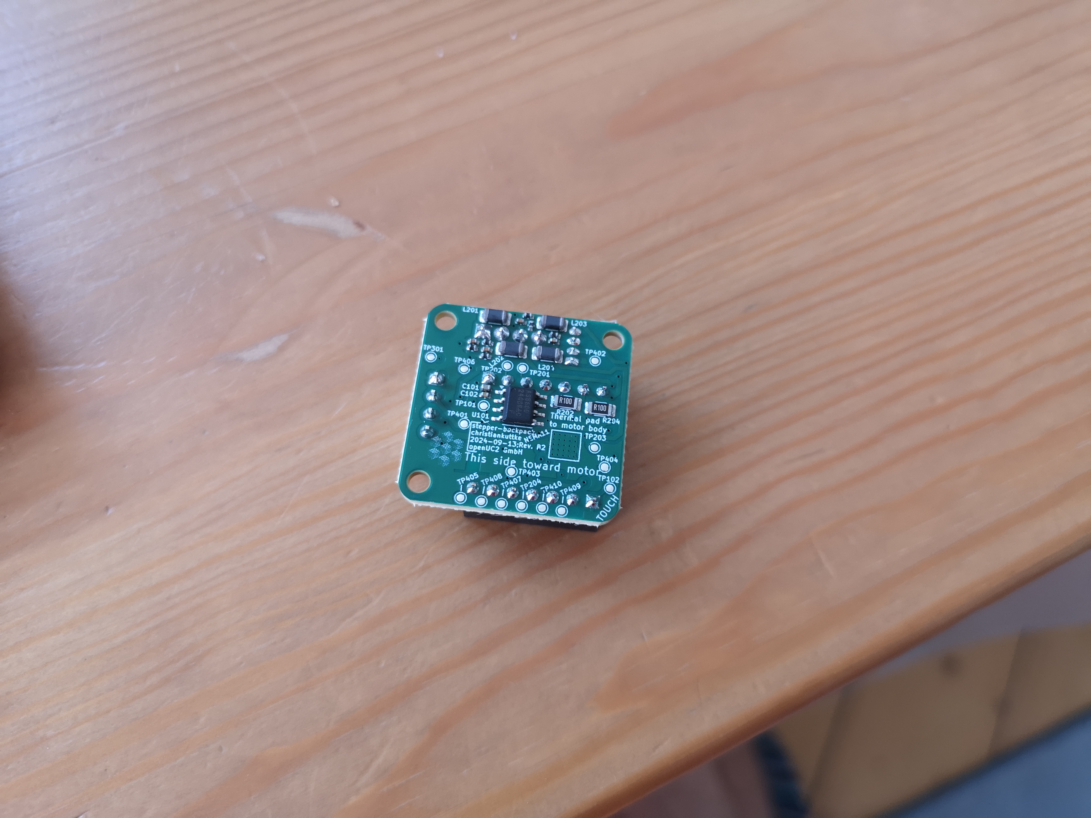
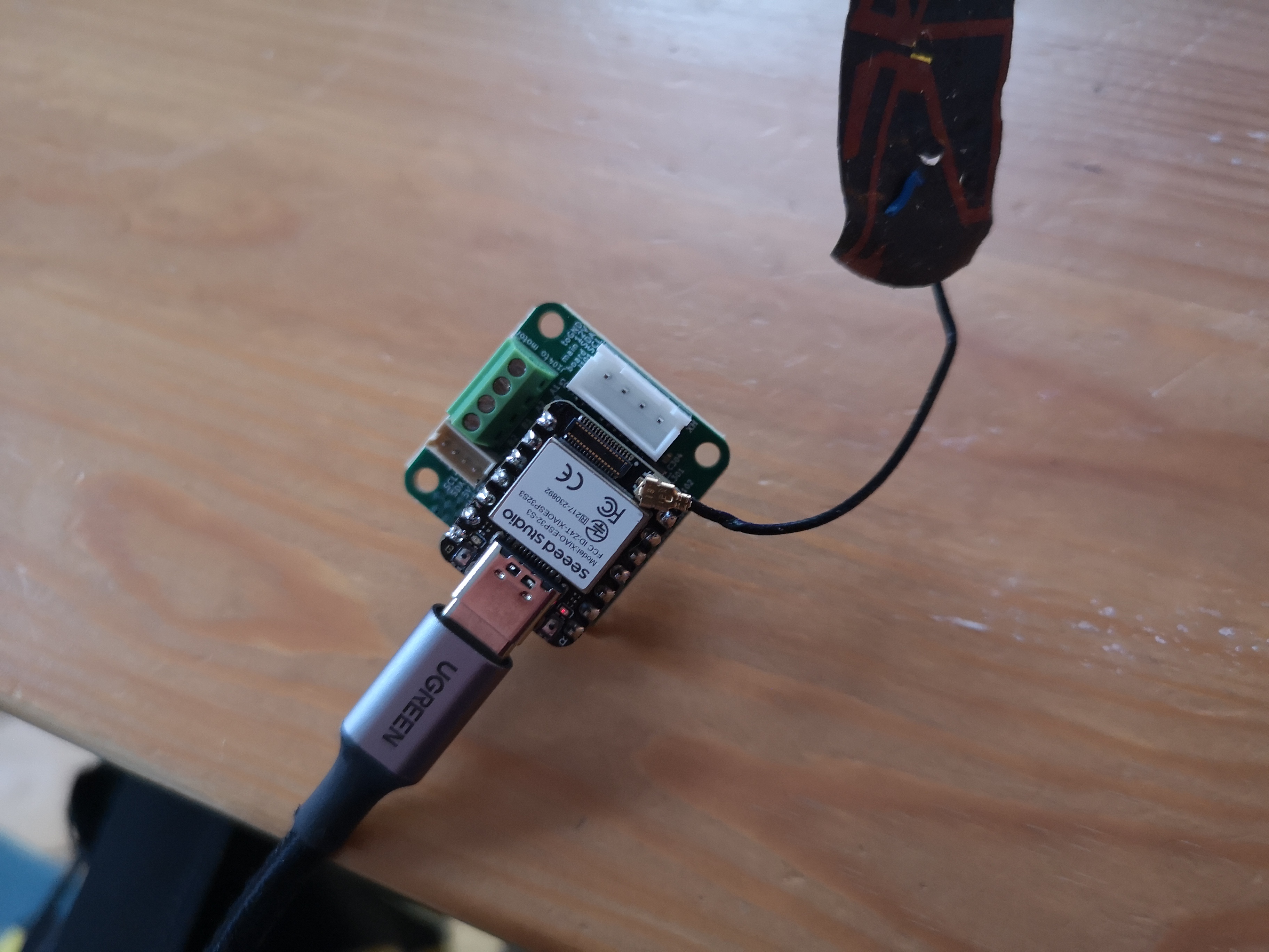
This motor controller is designed to control a stepper motor using the TMC2209 driver with optional feedback from a rotational encoder (AS5600). The XIAO ESP32-S3 handles communication and control.
| Interface | Current (CAN) revision |
|---|---|
| Firmware env | UC2_canopen_slave_motor (CAN satellite) |
| Node ID | default 11; CI builds _motA / _motX / _motY / _motZ = 10 / 11 / 12 / 13 |
| CAN | 500 kbit/s, CANopen; TX = D2 (GPIO3), RX = D1 (GPIO2) |
| Bus connector | JST-XH 4: 1 GND, 2 +12 V, 3 CAN_H, 4 CAN_L |
| Termination | JP502, 120 Ω, open by default; close only at a bus end |
| Serial | native USB-CDC of the XIAO, serial JSON (for testing without a bus) |
Node IDs, routing and the other satellites: Boards, roles & node IDs. Flashing, setting the node ID and wiring: Add a CAN satellite. Older revisions talked I2C to the master over D1/D2 (SCL/SDA).
Components:
- TMC2209 Stepper Driver: Manages the stepper motor's power and movement. It offers features like StallGuard for homing without limit switches.
- AS5600 Encoder: A magnetic encoder that tracks the stepper motor’s rotational position. Connected via I2C, it provides high-precision feedback for motor positioning.
Pin Descriptions:
- DIR (Direction): Controls the rotational direction of the stepper motor (Clockwise/Counter-Clockwise). Controlled via D8.
- STEP (Step Pulse): Sends pulses to the motor for each step. Controlled via D9.
- EN (Enable): D10.
- UART (TX/RX): The XIAO communicates with the TMC2209 driver for advanced functions such as StallGuard and diagnostics via UART on D6 (send) and D7 (receive).
- I2C (SDA/SCL): Connects the XIAO to the encoder. I2C pins on the XIAO are D4 (SDA) and D5 (SCL).
Power Requirements:
- 12V Input (JST-XH bus connector, pin 2): Powers the motor and is regulated to 5V and 3.3V via a DC-DC converter for the motor driver and encoder.
- 5V Input (old 5V+I2C revision only): The XIAO uses its internal regulator to supply 3.3V to the other components.
Features:
- StallGuard Functionality: This feature detects motor stall conditions and is useful for homing operations without mechanical limit switches.
- I2C Encoder (AS5600): Provides high-precision feedback on motor position, allowing for closed-loop control in certain applications.
Wiring:
-
Motor Wiring:
- Connect the motor windings to the respective outputs on the TMC2209.
- Windings A (A+, A-) and B (B+, B-) are connected to OA1, OA2, OB1, OB2 pins.
-
Encoder Wiring:
- SDA (I2C Data) to D4
- SCL (I2C Clock) to D5
-
Power and bus:
- JST-XH 4: 1 GND, 2 +12 V, 3 CAN_H, 4 CAN_L.
XIAO pin connections
Same as the FRAME electronics stepper-backpack pinout:
| XIAO pin | Function |
|---|---|
| D0 | Endstop |
| D1 | CAN RX (SCL on the old I2C bus) |
| D2 | CAN TX (SDA on the old I2C bus) |
| D3 | TMC2209 DIAG |
| D4 / D5 | I2C SDA / SCL to encoder |
| D6 / D7 | UART send to / receive from TMC2209 |
| D8 | DIR |
| D9 | STEP |
| D10 | EN |
Connections to Stepper Motor Controller (TMC2209):
- DIR: Controls the direction of the stepper motor.
- STEP: Steps the motor in the specified direction.
- UART_PICO: UART communication to the TMC2209 (TX from Xiao).
- UART_POCI: UART communication from the TMC2209 (RX to Xiao).
- I2C SDA / SCL: Communication with an external encoder (such as the AS5600 rotational encoder).
Code Example
Here’s a basic ESP32S3 code to control the TMC2209 stepper motor driver and AS5600 encoder (since AS5300 is typically a typo for AS5600, which is more common) in a feedback loop for 360° rotation in both directions. The code sets up the motor driver and encoder, reads the encoder's position, and runs the motor for a full revolution in either direction based on feedback from the encoder.
Required Libraries:
- TMCStepper for communicating with the TMC2209 driver.
- Wire for I2C communication with the AS5600 encoder.
Wiring:
- EN -> D10
- DIR (Direction) -> D8
- STEP (Step Pulse) -> D9
- I2C SDA -> D4
- I2C SCL -> D5
- UART TX -> D6
- UART RX -> D7
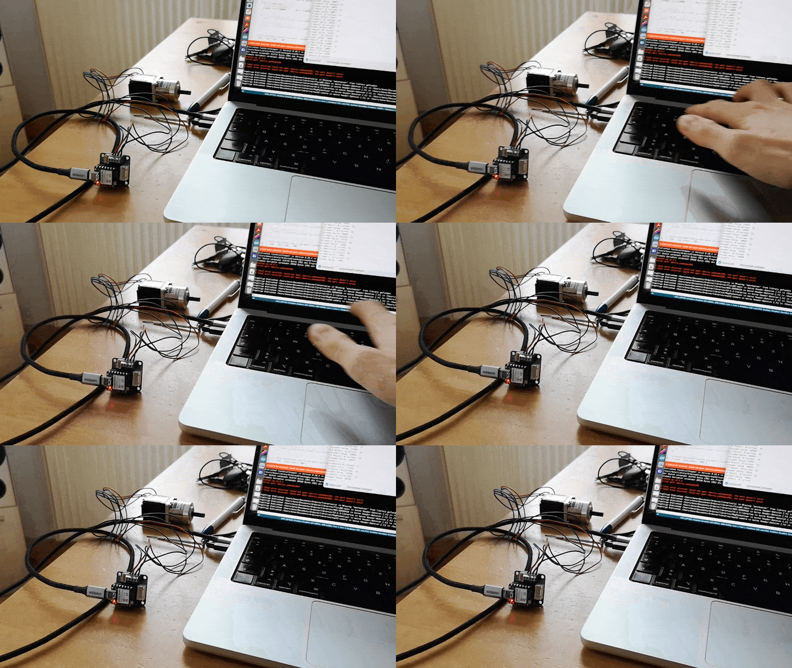
In Action:
Code:
Standalone test sketch (single-character commands 0/1 on the USB serial), not the UC2 firmware. The UC2 firmware for this board is the env UC2_canopen_slave_motor.
#include <FastAccelStepper.h> // Include the FastAccelStepper library
#include <TMCStepper.h>
#include <Wire.h>

// TMC2209 Settings
#define STALL_VALUE 100     // StallGuard sensitivity [0..255]
#define EN_PIN D10          // Enable pin for motor driver
#define DIR_PIN D8          // Direction pin
#define STEP_PIN D9         // Step pin
#define SW_RX D7            // UART RX pin for TMC2209
#define SW_TX D6            // UART TX pin for TMC2209
#define SERIAL_PORT Serial1 // UART Serial port for TMC2209
#define DRIVER_ADDRESS 0b00 // TMC2209 driver address
#define R_SENSE 0.11f       // Current sense resistor for TMC2209
#define MOT_DIAG D3

// AS5311 I2C Settings
#define SDA_PIN D4       // I2C SDA
#define SCL_PIN D5       // I2C SCL
#define AS5311_ADDR 0x36 // I2C address for AS5311

// Encoder settings
#define MAX_ENCODER_VALUE                                                      \
  16384 // AS5311 is a 14-bit encoder (2^14 = 16384 steps per revolution)

// FastAccelStepper setup
FastAccelStepperEngine engine =
    FastAccelStepperEngine();     // FastAccelStepper engine instance
FastAccelStepper *stepper = NULL; // FastAccelStepper instance

// TMC2209 instance
TMC2209Stepper driver(&SERIAL_PORT, R_SENSE, DRIVER_ADDRESS);

// Function to read AS5311 encoder value over I2C
int readEncoder() {
  Wire.beginTransmission(AS5311_ADDR);
  Wire.write(0x0C); // Register for reading high byte of encoder position
  Wire.endTransmission();
  Wire.requestFrom(AS5311_ADDR, 2);
  int high_byte = Wire.read();
  int low_byte = Wire.read();
  int position = (high_byte << 8) | low_byte;
  return position;
}

void setup() {
  Serial.begin(115200); // Init serial port and set baudrate
  while (!Serial)
    ; // Wait for serial port to connect
  Serial.println("\nStart...");

  // Start Serial communication for TMC2209
  SERIAL_PORT.begin(115200);

  // Pin setup for motor control
  pinMode(EN_PIN, OUTPUT);
  digitalWrite(EN_PIN, LOW); // Enable motor driver (LOW to enable)

  // Setup TMC2209 driver
  driver.begin();             // Initiate TMC2209
  driver.toff(4);             // Enable driver with off time
  driver.blank_time(24);      // Set blank time
  driver.rms_current(400);    // Set motor current to 400mA
  driver.microsteps(16);      // Set microstepping to 16
  driver.TCOOLTHRS(0xFFFFF);  // Set threshold for switching to StealthChop
  driver.semin(5);            // Enable StallGuard with minimum threshold
  driver.semax(2);            // Set maximum StallGuard threshold
  driver.sedn(0b01);          // Set StallGuard deceleration
  driver.SGTHRS(STALL_VALUE); // Set StallGuard sensitivity

  // Setup I2C for AS5311 encoder
  Wire.begin(SDA_PIN, SCL_PIN); // Initialize I2C with specified pins

  // FastAccelStepper setup
  engine.init(); // Initialize the FastAccelStepper engine
  stepper =
      engine.stepperConnectToPin(STEP_PIN); // Connect stepper to the STEP_PIN
  if (stepper) {
    stepper->setDirectionPin(DIR_PIN); // Set the direction pin
    stepper->setEnablePin(EN_PIN);     // Set the enable pin
    stepper->enableOutputs();          // Enable motor outputs
    stepper->setAutoEnable(true);      // Automatically enable motor when moving
    stepper->setSpeedInHz(10000);      // Set initial speed (steps per second)
    stepper->setAcceleration(10000);   // Set acceleration in steps/second^2
  }
}

void loop() {
  static uint32_t last_time = 0;
  uint32_t ms = millis();

  // Read encoder position and use it in feedback loop
  int encoderValue = readEncoder();

  // Control motor movement based on encoder feedback
  /*
  if (encoderValue < MAX_ENCODER_VALUE / 2) {
    stepper->moveTo(1000);  // Move forward by 1000 steps
  } else if (encoderValue >= MAX_ENCODER_VALUE / 2 && encoderValue <
  MAX_ENCODER_VALUE) { stepper->moveTo(-1000); // Move backward by 1000 steps
  }*/

  // Adjust speed via serial input
  while (Serial.available() > 0) {
    int8_t read_byte = Serial.read();
    if (read_byte == '0') {
      Serial.println("Stop");
      stepper->forceStop(); // Stop the motor
    } else if (read_byte == '1') {
      Serial.println("Start");
      stepper->move(10000); // Move forward by 1000 steps
    }
    /*
    else if (read_byte == '+') {
      stepper->setSpeedInHz(stepper->getSpeedInHz() + 100); // Speed up motor
    }
    else if (read_byte == '-') {
      stepper->setSpeedInHz(stepper->getSpeedInHz() - 100); // Slow down motor
    }*/
  }

  // Print StallGuard results and motor current every 100ms
  if ((ms - last_time) > 100) {
    last_time = ms;
    Serial.print("SG Result: ");
    Serial.print(driver.SG_RESULT(), DEC); // Print StallGuard value
    Serial.print(" Current: ");
    Serial.println(driver.cs2rms(driver.cs_actual()),
                   DEC); // Print motor current
    Serial.print("Encoder Value: ");
    Serial.println(encoderValue);
  }
}
Key Components:
- Setup TMC2209: The motor driver is initialized using UART communication and the current limit is set. StealthChop mode is enabled for quieter operation.
- Encoder Setup (AS5600): Uses I2C to read the encoder’s current position. The encoder provides feedback with a 12-bit resolution (4096 steps per revolution).
- MoveStepper Function: Moves the motor in a given direction (based on step count). The direction and steps are controlled using the DIR and STEP pins.
- Feedback Loop: The motor moves based on encoder feedback. If the encoder position is less than 180° (half of 4096 steps), the motor moves forward; otherwise, it moves backward to maintain a 360° operation.
Revision: CAN BUS
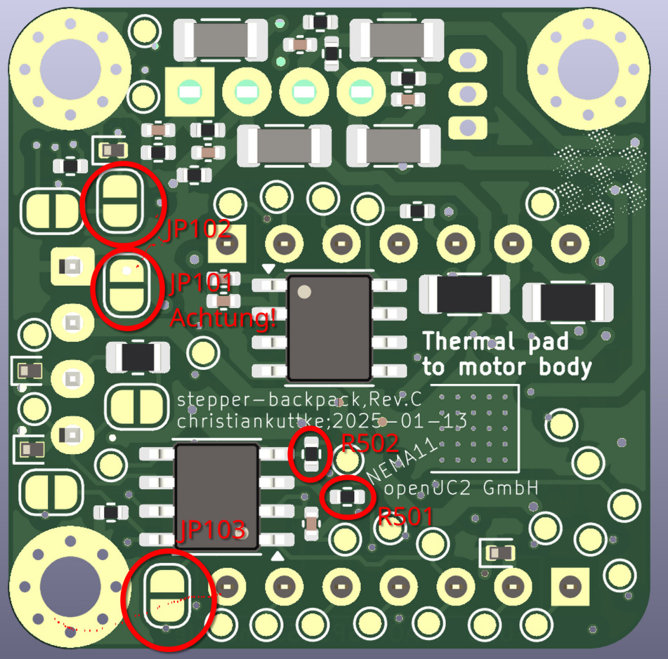
The CAN revision (Rev C, 2025-01) has a dedicated CAN transceiver on D1/D2 and power safety features. Firmware, node IDs and termination: see the table under Overview; pinout: see XIAO pin connections.
Attention:
Rev C can be converted between 12V+CAN and 5V+I2C with the marked jumpers and resistors. JP101 joins the 12 V and 5 V nets: never connect 12 V while it is closed. Details: FRAME electronics.