HAT+ v2
Technical specification, integration & bring-up guide
0) Quick links (hardware, firmware, docs)
- Schematics PDF (HAT+ Rev D): https://docs.openuc2.com/kicad/hatplus-for-raspberrypi-5.pdf
- Schematics PDF (Panel Board): https://docs.openuc2.com/kicad/hat-panelboard.pdf
- Firmware: env
UC2_canopen_master(section 11 below) - Serial and CANopen usage: Serial & CANopen interface, Boards, roles & node IDs
1) Purpose & feature summary
- HAT+ for Raspberry Pi (40-pin header) providing:
- 12 V input -> on-board 5.1 V / 5 A buck for Pi, plus 3.3 V LDO for the ESP32-WROOM-32 and various sensors, E-Stop logic and interface chips.
- Safety chain with Emergency-STOP (3.5 mm TRS) gating the 12 V output to the backbone. Momentary "Buspower OFF" button for quick cut.
- CAN bus for distributed module control:
- Raspi: MCP2515 SPI controller + SN65HVD230 transceiver
- ESP32: Built-in CAN (TWAI) controller + SN65HVD230 transceiver
- Optional 120 ohm termination and CAN activity LED by solder jumpers.
- ESP32-WROOM-32E CAN master (node 1; serial 921600 baud via USB-C + CP2102 or the Pi UART; flashable via Pi UART with auto-program DTR/RTS).
- Sensors & I/O:
- INA226 current sensor (I2C addr 0x46)
- two TMP102 temperature sensors (I2C addrs typically 0x4A and 0x4B)
- NeoPixel header/extend, camera trigger out, fan tacho feedback, front-panel header
- Dual HAT+ EEPROMs (Standard class + Power MODE1 class "5 A capable") for automatic OS configuration. (not working currently, workaround through our Raspi OS)
2) Electrical architecture
2.1 Power path (12 V in -> 5 V / 3.3 V)
- Input: Barrel jack J101 (5.5 mm OD / 2.5 mm ID, center-positive), protected by a 7 A resettable fuse. Backfeed/ESD diodes protect rails and ports.
- Buck: TI TPS54560 set to about 5.1 V, rated for 5 A continuous (thermal-limited), with output network sized for step loads (design spreadsheet notes in schematic).
- LDO: AMS1117-3.3 (up to 1 A) generating 3.3 V for logic/sensors from the 5 V rail.
- Indicators & supervisors:
- 5 V present / OK window with MAX809 (2.93 V threshold in sensing chain) driving red/green LEDs (D401/D402). 5 V "OK" when above about 4.9 V.
- 3.3 V and switched 12 V likewise instrumented with LEDs/supervisors for fast bring-up diagnosis.
2.2 High-current "bus power" switching & safety
- Emergency-STOP chain (TRS jack J501): tip-ring must be normally closed externally; opening latches OFF.
- Sleeve supplies LED ground for the external box; power budget about 33 mA at 3.3 V.
- Main bus power switch: PMOS (Q602) producing
+12V_switched- Gate logic is driven by
BUSPOWER_ENand hard-gated by E-STOP and "buspower-off" lines. BUSPOWER_ENhas to be actively driven HIGH to turn on the big PMOS (see schematic note).
- Gate logic is driven by
- Bypasses (for troubleshooting only):
- JP601 "circumvent-buspower-switch": forces main PMOS ON (disables E-STOP, use only for lab debugging).
- JP201 "circumvent-power-software-switching": prevents Pi/ESP from cutting bus power via GPIO (safety-critical behavior may be altered).
3) Communication & control
3.1 Raspberry Pi interface (physical pin numbers)
- 3 (SDA1) / 5 (SCL1): I2C-1
- Solder jumpers JP101/JP102 can bridge Pi I2C to the board's shared I2C net (and to the ESP32 I2C if you close the bridge).
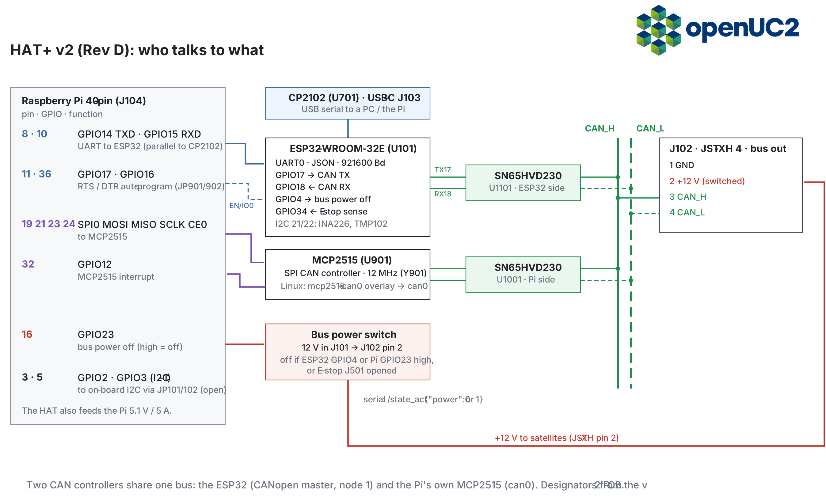
- 8 (GPIO14 TXD) / 10 (GPIO15 RXD): UART to ESP32, 921600 baud (paralleled with CP2102).
- 11 (GPIO17) / 36 (GPIO16): RTS / DTR for ESP32 auto-program (same lines as the CP2102). Open JP901/JP902 to isolate if needed.
- 16 (GPIO23): buspower-off when HIGH (wired into the power gating logic).
- 19/21/23/24: SPI0 (MOSI/MISO/SCLK/CE0) to MCP2515.
- 32 (GPIO12): MCP2515 INT.
- 26 (GPIO7) / 27 (GPIO0): SCL / SDA of the HAT+ EEPROMs. The HAT+ specification expects ID_SC on pin 28; on this PCB the EEPROM SCL goes to pin 26, which may explain why the EEPROMs are not detected.
3.2 ESP32 pinout (Rev D / v2, used signals)
Matches the Rev D netlist and the firmware env UC2_canopen_master (main/config/UC2_canopen_master/PinConfig.h):
| ESP32 GPIO | Net / Function | Notes |
|---|---|---|
| 21 | I2C-1 SDA | Shared sensor bus |
| 22 | I2C-1 SCL | Shared sensor bus |
| 17 | CAN TX (TWAI, ESP_CAN-SEND) | To ESP-side SN65HVD230 |
| 18 | CAN RX (TWAI, ESP_CAN-RECV) | From ESP-side SN65HVD230 |
| 19 | NeoPixel data | On-board WS2812 + neopixel-extend |
| 27 | Camera trigger out (camera-trigger_esp-gpio) | To Panel Board; firmware CAMERA_TRIGGER_PIN |
| 33 | Fan tacho in | From Panel Board |
| 32 | – | Test point only |
| 25 | Buzzer (active HIGH) | |
| 35 | ALERT (sensors) | Input-only |
| 4 | BUSPOWER_OFF (HIGH = off) | Software cut of +12V_switched |
| 34 | E-STOP sense (sense-emg-stop) | Input-only pin; HIGH = E-STOP asserted |
4) I2C pins
Raspberry Pi I2C (primary)
- Pi I2C-1 is on header pins:
- Pin 3: GPIO2 / SDA1
- Pin 5: GPIO3 / SCL1
ESP32 I2C (on the HAT)
- ESP32 uses:
- GPIO21 = SDA
- GPIO22 = SCL
Bridging Pi ↔ ESP I2C
- JP101 (SDA) and JP102 (SCL) are the solder jumpers that connect the Pi I2C-1 lines into the HAT shared I2C net (and therefore to the ESP32 I2C pins and the I2C header ecosystem).
- Open by default. The Pi (
i2cdetect -y 1) only sees the on-board INA226/TMP102 when JP101 and JP102 are closed.
- Open by default. The Pi (
Practical note: the Pi has its own pullups on I2C-1. If the Pi is unpowered, the bus can behave oddly or backpower through pullups, so treat shared I2C with care when mixing power domains.
5) Temperature sensor (which one, pins, addresses)
- The HAT has two TMP102 temperature sensors on the shared I2C bus.
- Typical addresses on this design: 0x4A (ambient) and 0x4B (PCB temp), depending on ADDR strap.
- Pins:
- They sit on I2C-1 SDA/SCL (shared bus): ESP32 GPIO21/22 and optionally Pi pins 3/5 if bridged by JP101/JP102.
- ALERT:
- TMP102 supports ALERT, routed as open-drain in the design (board-level integration exists but may be left unpopulated or unused in firmware).
6) Buzzer (how it works)
- The buzzer is a 3.3 V driven beeper (BZ1501) switched by an NPN transistor (Q1501 SS8050).
- Signal is
buzzer-input(ESP32 GPIO25, active HIGH) into a base resistor network (R1501 5.6k, etc.). The transistor sinks current through the buzzer. - Recommended drive for loudest beep:
- 2.7 kHz, 50% duty cycle PWM.
- Arbitrary waveforms also work.
7) Emergency stop (how to detect)
Hardware behavior
- E-STOP is a TRS 3.5 mm jack (J501):
- Remote box uses an NC switch between Tip and Ring.
- Opening the loop triggers the safety chain and disables
+12V_switched(latched OFF by the gating logic).
- There is also an "override" (SW501 /
emg-stop_OVERRIDE) intended as a last-resort field bypass, protected against accidental use.
Firmware detection (ESP32)
- Read the E-STOP sense net on ESP32:
sense-emg-stopis wired to GPIO34 (input-only).- Logic on this board: HIGH = E-STOP asserted, LOW = operational (normal).
Pseudo-code:
pinMode(34, INPUT);
bool estop_hit = (digitalRead(34) == HIGH);
8) Switching off 12 V from ESP32 or Raspberry Pi
The switched 12 V rail (+12V_switched) can be shut off in two ways:
8.1 Software kill (fast, intended)
-
Two "buspower-off" lines are wired into the power gating logic:
- ESP32:
buspower-off_ESPon GPIO4 (HIGH = OFF) - Raspberry Pi:
buspower-off_raspion GPIO23 (Pi header pin 16; HIGH = OFF)
- ESP32:
This is a hard gate: if either line requests OFF, the switched 12 V is disabled. From the host: {"task":"/state_act","power":0} (1 = on).
8.2 Physical kill (local momentary)
- SW601 is a momentary "Buspower OFF" that forces OFF in hardware.
9) CAN activity and termination (which solder jumpers to bridge)
These are the useful field jumpers for CAN diagnostics and bus correctness:
-
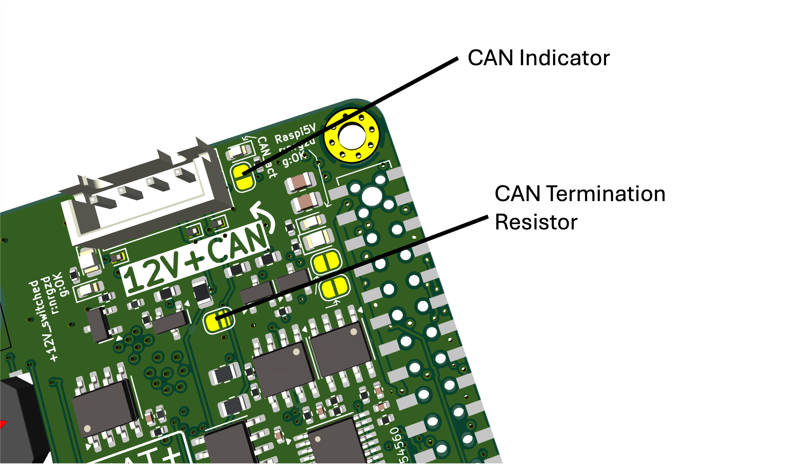
JP801: enable on-board 120 ohm termination
- Open by default. Bridge it only if this node is at one end of the CAN bus (one terminator per end).
-
JP802: enable CAN dominant-state indicator LED
- Helpful to visually confirm activity (adds a small load to the bus).
Other jumpers worth knowing:
- JP101 / JP102: bridge Pi I2C SDA/SCL into the shared I2C net (only if you want a shared bus).
- JP601 and JP201: bypass safety behavior (debug only, not for normal operation or shipping).
10) High current mode (reproducible activation, automated)
Goal: reliably allow high USB current draw on Raspberry Pi 5 (and avoid brownouts) by combining:
- correct power hardware (5.1 V / 5 A capability), and
- OS configuration that lifts the Pi USB current policy.
10.1 Current workaround (works today)
Add this to /boot/firmware/config.txt:
usb_max_current_enable=1
More information about that here: https://github.com/openUC2/os-rpi/pull/48
This is OS-image controllable (automate it in your openUC2 OS build / image pipeline).
10.2 Intended automated method (HAT+ EEPROM)
The design contains two HAT+ EEPROMs on the Pi EEPROM I2C lines (pins 26/27, see 3.1) to advertise the HAT class, including a Power MODE1 class ("5 A capable") so the Pi can lift power limits automatically.
Status: on early bring-up this is "not working currently" in the project notes, so keep the config.txt method in place until EEPROM programming + detection is validated end-to-end.
11) Firmware (ESP32 CAN master)
| Env | UC2_canopen_master (_release / _debug variants) |
| Role | CAN master, node 1, CANopen at 500 kbit/s |
| Serial | 921600 baud, USB-C (CP2102) or Pi UART pins 8/10 |
| Web flasher | youseetoo.github.io/flasher.html, board UC2 CAN Master |
| Image | esp32_UC2_canopen_master_release.bin (_merged.bin for a full flash at 0x0) |
Satellites (motors, laser, LED, galvo) are reached through the master's routing table; see Boards, roles & node IDs.
12) Panel Board (more information)
The Panel Board is a small front-panel / breakout PCB powered by the HAT and intended to:
-
Provide convenient connectors for:
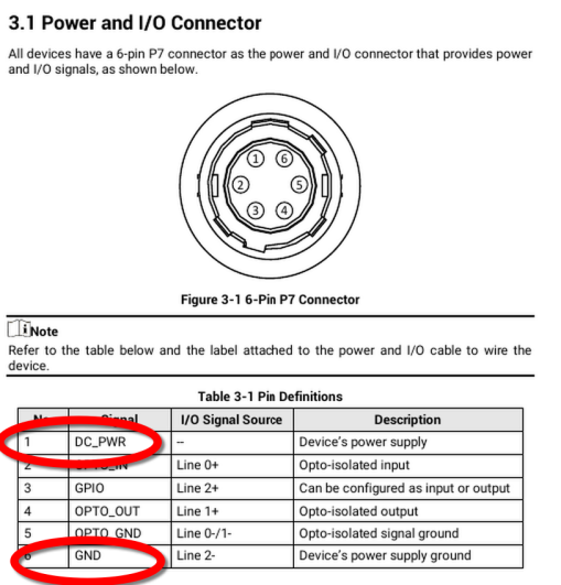
- STEMMA / STEMMA QT I2C at 3.3 V
- 5 V addressable LED headers (ARGB-style)
- SMA camera trigger output (for HIKROBOT camera Line 0)
- Fan header with tacho and controllable supply
12.1 Panel Board input connector from HAT (J101, 7-pin)
The harness from HAT to Panel Board carries:
I2C_SDAI2C_SCLneopixel(data)camera-trigger_esp-gpiofan_tachoGND+12V
The Panel Board generates its local 5 V and 3.3 V from the 12 V input.
12.2 STEMMA / STEMMA QT (I2C expansion)
-
Two connectors:
- JST-PH STEMMA (J107)
- JST-SH STEMMA QT (J106)
-
Output: 3.3 V + I2C, with max about 200 mA average (design note: 1 A peak), pullups are on the HAT (so do not duplicate aggressively).
12.3 5 V LED headers (ARGB / NeoPixel ecosystem)
-
LED headers provide:
- 5 V (up to 3 A from the local 12 -> 5 V buck on the Panel Board)
- NeoPixel data
- GND
-
There are multiple header styles to match common PC ARGB ecosystems (notes in schematic).
12.4 Camera trigger output to HIKROBOT (SMA)
-
The Panel Board includes a level interface that takes the ESP32 3.3 V trigger (
trigger_from-ESP) and drives a 12 V level suitable for the camera input (HIKROBOT Cam In Line 0). -
Implementation:
- NPN transistor + PMOS high-side stage (AO3401A) to drive the camera optoisolator input correctly.
-
Important notes from the schematic:
- Camera input is effectively an optocoupler LED with an internal resistor and needs a minimum voltage.
- This board drives a "12 V signal level" to meet the camera input requirements.
12.5 Fan header and controllable fan supply
-
The Panel Board provides a 3-pin fan connector (J401) with:
- GND
Tacho(open-drain from fan)- a controllable supply rail (
DCDC_FAN_VOUT)
-
Fan supply generation:
- A buck converter stage that can produce a variable output (design notes indicate 12 V down to about 3 V).
- Control uses an I2C digital potentiometer MCP4017 at I2C address 0x2F (design note).
- There is a local 3.3 V LDO supply dedicated for the fan control subsystem.
13) Linux integration (CAN & sensors)
13.1 MCP2515 overlay (Pi-side CAN on Linux)
- SPI0 CE0 (CS), INT at GPIO12, SCK/MOSI/MISO on pins 23/19/21.
- Crystal Y901 is 12 MHz.
/boot/firmware/config.txt:
dtparam=spi=on
dtoverlay=mcp2515-can0,oscillator=12000000,interrupt=12,spimaxfrequency=10000000
Then:
sudo apt install can-utils
sudo ip link set can0 up type can bitrate 500000 restart-ms 100
candump can0
Walk-through with node discovery and a motor move: CANopen from the Raspberry Pi.
13.2 Sensors (I2C)
Requires JP101/JP102 closed (open by default; otherwise the sensors are only on the ESP32 I2C bus).
sudo apt install i2c-tools
i2cdetect -y 1
Expected addresses:
- INA226: 0x46
- TMP102: typically 0x4A and 0x4B
14) Field solder-jumpers quick table
| Jumper | Action |
|---|---|
| JP801 | Add 120 ohm CAN termination |
| JP802 | Enable CAN dominant-state LED |
| JP101 | Bridge Pi I2C SDA into shared I2C net |
| JP102 | Bridge Pi I2C SCL into shared I2C net |
| JP601 | Force bus power ON (bypass E-STOP) |
| JP201 | Disable Pi/ESP software power-off |
| JP901/JP902 | Open to isolate Pi from CP2102 RTS/DTR |
15) Appendix: default pin maps
15.1 Default Raspberry Pi header map (summary)
| Pin | Function |
|---|---|
| 3 / 5 | I2C-1 SDA/SCL (bridgeable via JP101/JP102) |
| 8 / 10 | UART TX/RX to ESP, 921600 baud (paralleled with CP2102) |
| 11 / 36 | RTS / DTR auto-program (JP901 / JP902) |
| 16 | buspower-off (HIGH = off) |
| 19/21/23/24 | SPI0 MOSI/MISO/SCLK/CE0 -> MCP2515 |
| 26 / 27 | EEPROM SCL / SDA -> HAT+ EEPROMs (spec: ID_SC is pin 28) |
| 32 | MCP2515 INT (GPIO12) |
15.2 ESP32 used pins (summary)
| GPIO | Function |
|---|---|
| 21 / 22 | I2C SDA/SCL |
| 17 / 18 | CAN TX/RX (TWAI) |
| 19 | NeoPixel |
| 4 | BUSPOWER_OFF (HIGH = off) |
| 34 | E-STOP sense (HIGH = asserted) |
| 27 | Camera trigger out |
| 33 | Fan tacho in |
| 25 | Buzzer |
15.3 Trigger wiring for the HIK camera
Camera opto input pin 2 = yellow, camera opto GND pin 5 = white, both soldered to the SMA connector. More info: openUC2/TechnicalDocs-openUC2-FRAME#134