HAT+ v1
HAT for the Raspberry Pi 5 with an ESP32 that drives motors and illumination modules over CAN (CANopen, 500 kbit/s) and optionally I2C. Overview and v1/v2 differences: HAT+. Bus, pins and node IDs: Boards, roles & node IDs.
Pinout
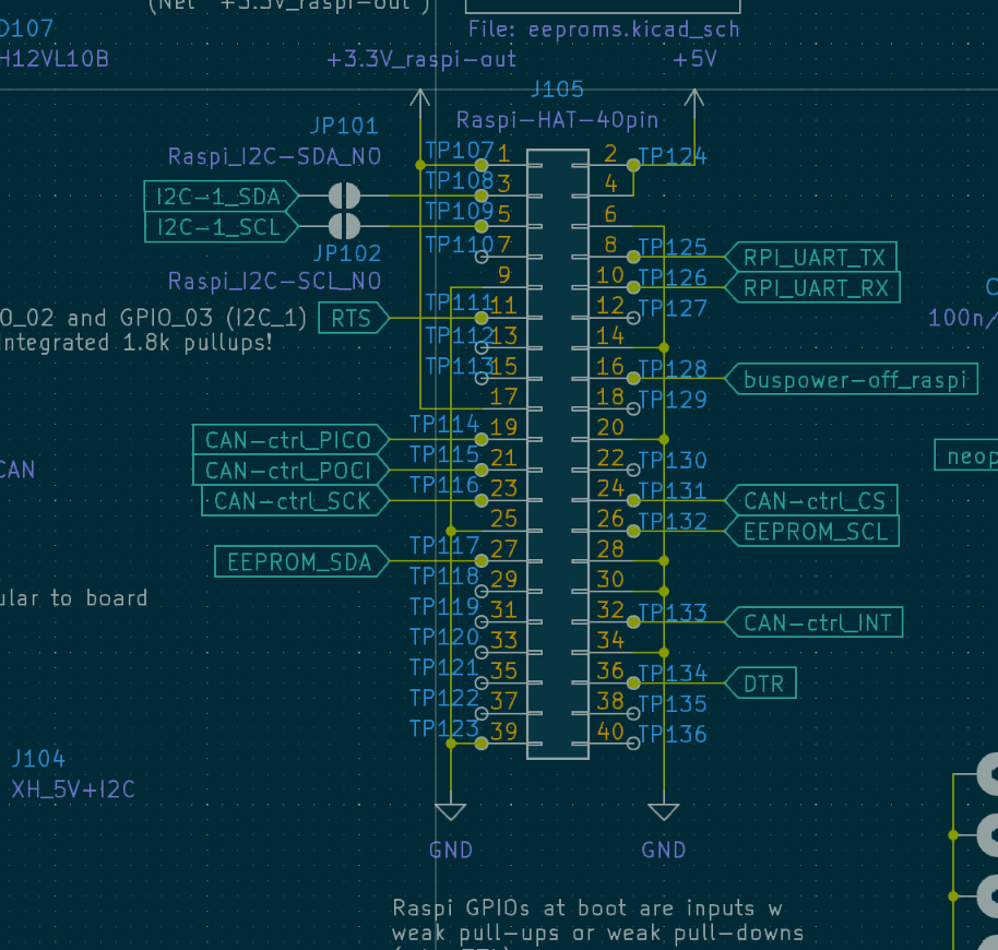
Raspberry Pi header as used by the HAT (physical pin → function):
raspi_pinheader = {
    1: {"Pin": 1, "Function": "+3.3V"},
    2: {"Pin": 2, "Function": "+5V"},
    3: {"Pin": 3, "Function": "I2C_1_SDA (GPIO2)"},
    4: {"Pin": 4, "Function": "+5V"},
    5: {"Pin": 5, "Function": "I2C_1_SCL (GPIO3)"},
    6: {"Pin": 6, "Function": "GND"},
    7: {"Pin": 7, "Function": "GPIO4"},
    8: {"Pin": 8, "Function": "RPI_UART_TX (GPIO14)"},
    9: {"Pin": 9, "Function": "GND"},
    10: {"Pin": 10, "Function": "RPI_UART_RX (GPIO15)"},
    11: {"Pin": 11, "Function": "ESP auto-program RTS (GPIO17)"},
    12: {"Pin": 12, "Function": "GPIO18"},
    13: {"Pin": 13, "Function": "GPIO27"},
    14: {"Pin": 14, "Function": "GND"},
    15: {"Pin": 15, "Function": "GPIO22"},
    16: {"Pin": 16, "Function": "buspower-off, HIGH = off (GPIO23)"},
    17: {"Pin": 17, "Function": "+3.3V"},
    18: {"Pin": 18, "Function": "GPIO24"},
    19: {"Pin": 19, "Function": "CAN-ctrl_PICO (GPIO10)"},
    20: {"Pin": 20, "Function": "GND"},
    21: {"Pin": 21, "Function": "CAN-ctrl_POCI (GPIO9)"},
    22: {"Pin": 22, "Function": "GPIO25"},
    23: {"Pin": 23, "Function": "CAN-ctrl_SCK (GPIO11)"},
    24: {"Pin": 24, "Function": "CAN-ctrl_CS (GPIO8)"},
    25: {"Pin": 25, "Function": "GND"},
    26: {"Pin": 26, "Function": "EEPROM_SCL (GPIO7)"},
    27: {"Pin": 27, "Function": "EEPROM_SDA (GPIO0, ID_SD)"},
    28: {"Pin": 28, "Function": "ID_SC (GPIO1)"},
    29: {"Pin": 29, "Function": "GPIO5"},
    30: {"Pin": 30, "Function": "GND"},
    31: {"Pin": 31, "Function": "GPIO6"},
    32: {"Pin": 32, "Function": "CAN-ctrl_INT (GPIO12)"},
    33: {"Pin": 33, "Function": "GPIO13"},
    34: {"Pin": 34, "Function": "GND"},
    35: {"Pin": 35, "Function": "GPIO19"},
    36: {"Pin": 36, "Function": "ESP auto-program DTR (GPIO16)"},
    37: {"Pin": 37, "Function": "GPIO26"},
    38: {"Pin": 38, "Function": "GPIO20"},
    39: {"Pin": 39, "Function": "GND"},
    40: {"Pin": 40, "Function": "GPIO21"},
}
The EEPROM SCL goes to pin 26 (GPIO7), not to ID_SC on pin 28 as the HAT+ specification expects (same routing on v2); this may be why the Pi does not detect the HAT EEPROM.
ESP32
The ESP32-WROOM-32E runs the CAN master firmware (env UC2_canopen_master, node 1). It takes serial JSON at 921600 baud from USB-C (CP2102) or the Pi UART (pins 8/10) and forwards commands over CAN.
| ESP32 GPIO | Function |
|---|---|
| 17 | CAN TX (ESP_CAN-SEND) |
| 18 | CAN RX (ESP_CAN-RECV) |
| 19 | NeoPixel |
| 21 / 22 | I2C-1 SDA / SCL |
| 4 | bus power off (HIGH = off) |
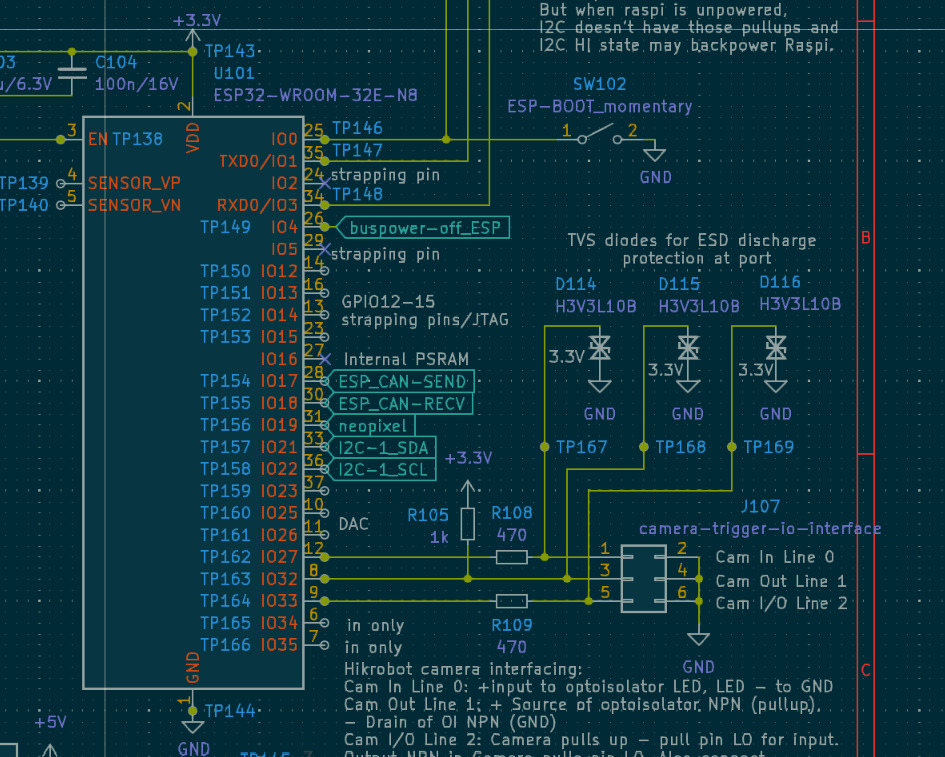
| 27 / 32 / 33 | camera trigger Line 0 in / Line 1 out / Line 2 I/O |
HAT+ on Jetson
Bus power and termination
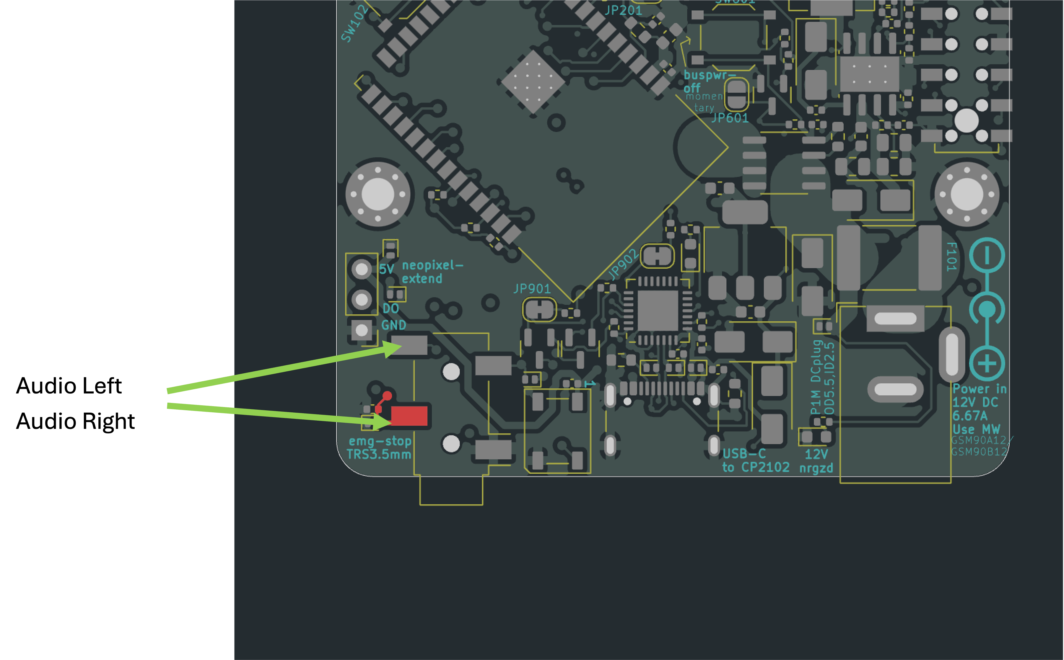
The 12 V on the CAN connector is only switched on when the E-stop loop on the 3.5 mm jack is closed (NC switch between Tip and Ring). Without an E-stop box, bridge Tip and Ring at the marked pads:
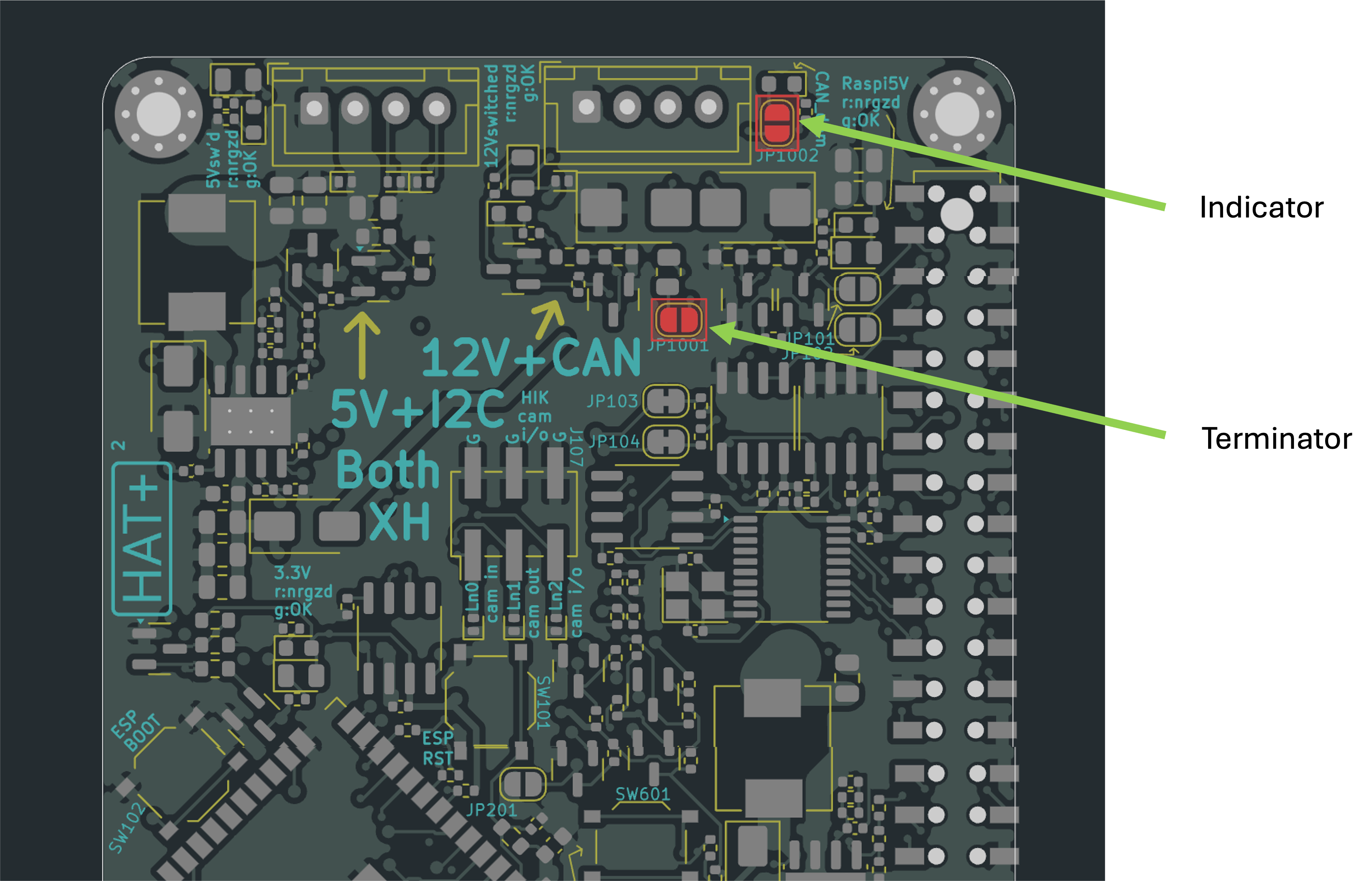
Close JP1001 for the 120 Ω CAN termination (only if the HAT is at one end of the bus) and JP1002 for the CAN activity LED:
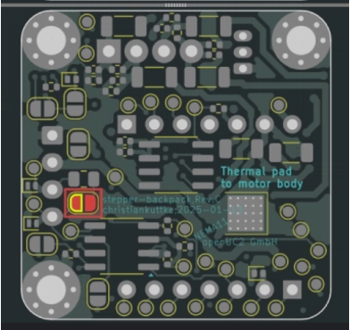
The other end of the bus needs the same 120 Ω termination, e.g. JP502 on the stepper backpack (Rev C):