UC2 Standalone Board v4
🔌 Board layout and schematics (UC2 Standalon v4)
The board comes with 4 motor controllers (e.g. A4988 Bipolar Stepper controller or TMC drivers with pololu pinout), the ESP32 Dev Kit, a bunch of pins for in/outgoing connections, 3 darlington transistors (BD809) and the power distribution. It is inspired by the CNC shield and can
- run up to 4 steppers
- run multiple high power LEDs
- be controlled via PS3/PS4 Controllers
- drive Adafruits Neopixels
- trigger a Camera
- provide scanning patterns for Galvos
- control/readout external devices using I2C
We use the ESP32 in order to ensure connectivity via
- Wifi
- Bluetooth
- USB Serial (mostly used)
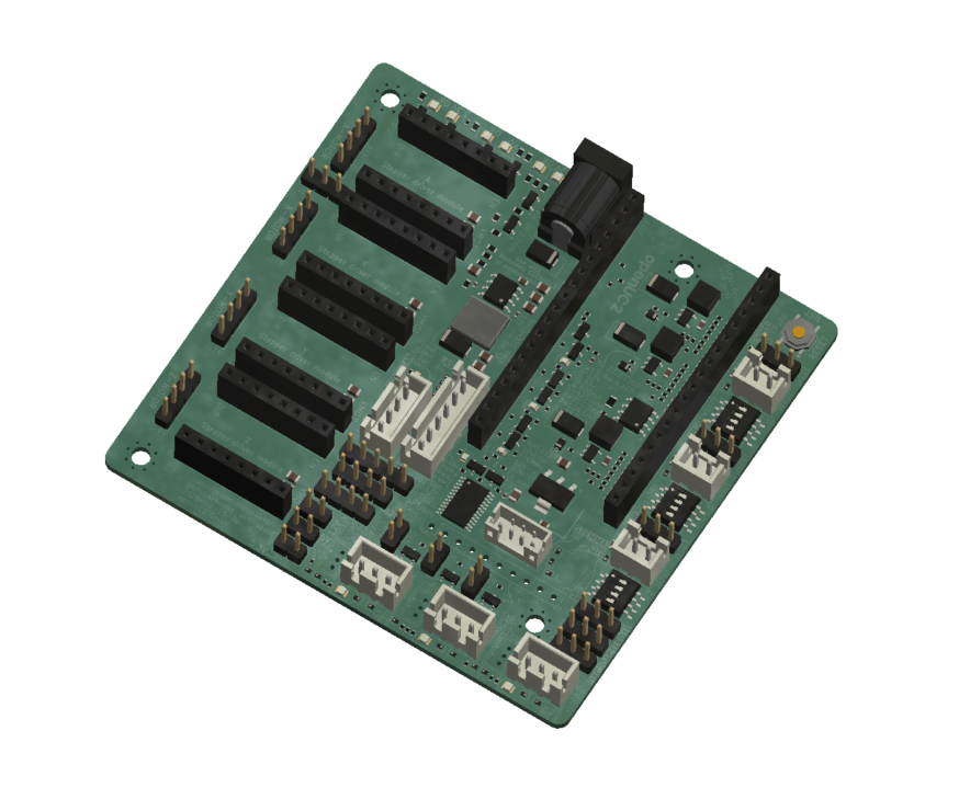
pinouts
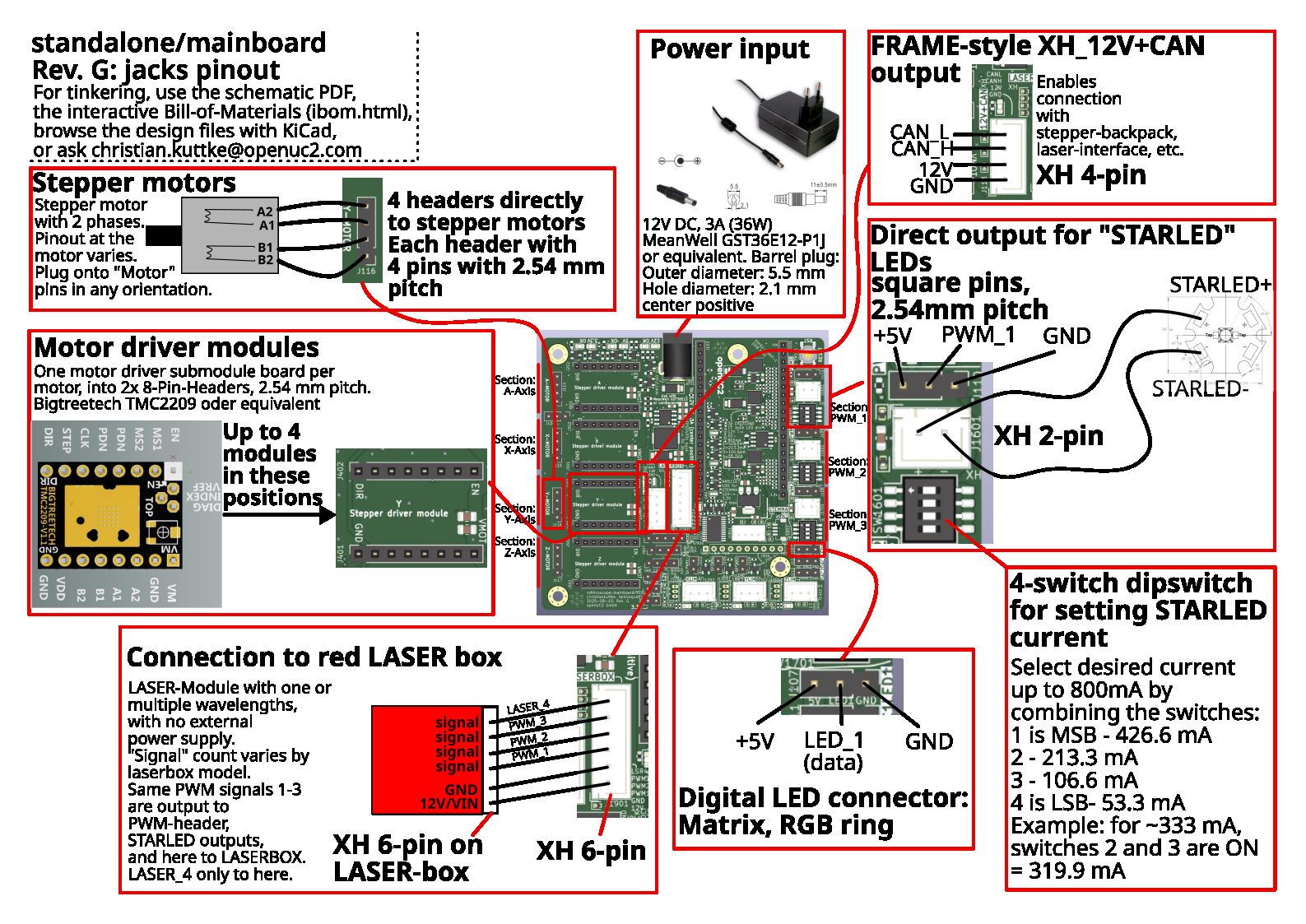
Interfaces
UC2_4 | UC2_canopen_standalone_v4_release | |
|---|---|---|
| Role | standalone, CAN unused | CAN master, node 1 (hybrid) |
| Serial | USB, 115200 baud, serial JSON | USB, 115200 baud, serial JSON |
| CAN | – | 500 kbit/s, TX GPIO32 / RX GPIO33, on the "XH_12V+CAN" output |
| Via CAN | – | illumination board (node 30: LED + laser id 4), galvo (node 40) |
USB-serial chip: CP2102 or CH340, depending on the ESP32 DevKit. Both envs drive the on-board devices directly:
| Function | ESP32 GPIO |
|---|---|
| STEP A / X / Y / Z | 15 / 16 / 14 / 0 |
| DIR, enable | TCA9535 I/O expander, I2C 0x27 (SDA 21, SCL 22) |
TMC2209 UART, 4 drivers (UC2_canopen_standalone_v4_* only) | TX 26 / RX 34 |
| Laser / PWM 1 / 2 / 3 | 12 / 4 / 2 |
| LED data (64 px) | 13 |
In the hybrid build, extra CAN motors (stepper id ≥ 4) are not routed by the current firmware. See Serial & CANopen interface and First serial command.
connecting devices - max. configuration for Discovery line products
- connect the LED-Matrix to the Mainboard at
LED1. - Connect the Z-stage to the position
Z-Motoron the main board. Ensure there's a motor driver. - Connect the 3 Motors of the XYZ-Stage to the respective positions
A-Motor,X-Motor,Y-Motor. Ensure there are motor drivers as well. - Connect the single fluorescence LED at
PMW2. - Connect the single-color laser to the Mainboard at
XH 4-pinor the dual-color laser atXH 6-pin. In the Webserial you control it with the PMW1 buttons - Plug in the USB-micro/USB-C at your ESP32 and connect to your PC.(USB-type depends on ESP32-type)
- Plug in the 12V power cable.