Electronics and safety functions (ID10–ID20)
One 12 V supply feeds a Raspberry Pi 5 with the HAT+ and a CAN bus that carries power and data to every motor, laser and lamp board. This page lists the boards, says what the emergency stop and the laser interlock do, and what they do not do.
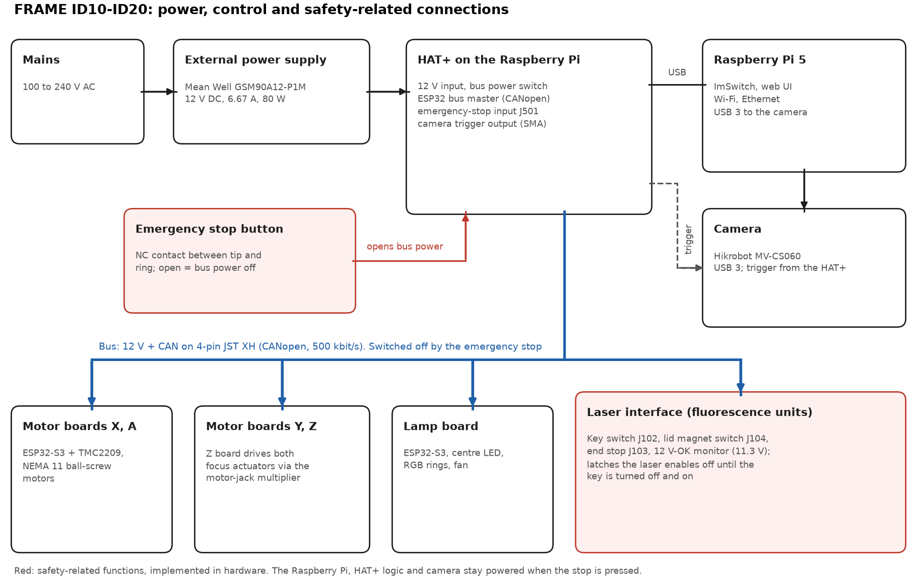
For the bus protocol and node IDs see Electronics and controllers. Schematics are in the repository FRAME-electronics-hardware.
Power
| Item | Value |
|---|---|
| Supply | Mean Well GSM90A12-P1M, 12 V DC, 6.67 A, 80 W, medical-grade desktop unit |
| Plug | barrel, 5.5 mm outside, 2.5 mm inside, centre positive, into the HAT+ |
| Mains | 100 to 240 V AC at the supply; no mains voltage inside the microscope |
| Power switch | none. Shut down in ImSwitch, wait 30 s, pull the plug |
| Rails on the HAT+ | 12 V switched (bus), 5 V switched (bus), 5 V for the Raspberry Pi, 3.3 V; one status LED per rail |
| Fuse | F101 on the HAT+; rating not documented |
Boards in a unit
| Board | Where | Function |
|---|---|---|
| Raspberry Pi 5 with active cooler and NVMe base | electronics box, under the stage at the back | runs ImSwitch; USB 3 to the camera |
| HAT+ for Raspberry Pi 5 (Rev. E) | on the Pi | ESP32 bus master, CAN transceiver, bus power switch, emergency-stop input, camera I/O header |
| HAT panel board | back panel | connectors to the outside |
| Stepper backpack (Rev. D, NEMA 11) with XIAO ESP32-S3 | X and A under the stage base plate; Y and Z on the Y plate | one driver and one bus node per axis; own USB-C port for flashing |
| XH connector hub, hub miniaturized (Rev. G) | stage, lamp arm | bus distribution |
| Drag-cable terminal, end-stop jack multiplier, motor jack multiplier | stage | wiring of the moving axes |
| Linear encoder interfacer (Rev. A3) | at each magnetic strip | encoder read-out |
| Illumination board with ring LEDs (Rev. E) with XIAO ESP32-S3 | lamp head | centre LED, RGB rings, fan |
| Laser interface | laser module (fluorescence units) | laser enable signals, key switch, interlock |
| CAN GPIO board (FR120) | stage | force sensor, extra inputs |
Three fans run in a unit: Pi cooler, a 40 mm fan in the electronics box and a 30 mm fan on the lamp.
Back panel
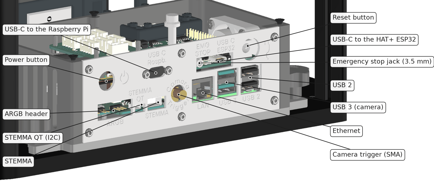
| Connector | Use |
|---|---|
| Power button | marked ⏻ on the panel |
| USB-C, "Raspb." | network link to the Raspberry Pi over USB, for a computer that does not use the hotspot |
| USB-C, "ESP32" | USB-C of the HAT+ ESP32: firmware and serial access |
| EMG STOP | 3.5 mm jack for the external emergency stop, see below |
| Reset button | reset, next to the ESP32 port |
| Camera trigger | SMA, trigger output to the camera |
| LAN, USB 3, USB 2 | Raspberry Pi: network, camera (blue USB 3), accessories |
| ARGB, STEMMA QT, STEMMA | Panel board: addressable LED strip, I2C sensors |
The 12 V input is the barrel jack of the HAT+. It is reached from the side of the electronics box, not from the back panel. Plug it in last.
Bus
- CANopen at 500 kbit/s on 4-pin JST XH: ground, +12 V, CAN high, CAN low.
- Termination by solder jumper on the HAT+ (JP1001) and on the far node.
- JST XH plugs hold by friction. On the first series the lamp cable must be plugged in reversed; check the label on your unit.
- The Y motor, both focus actuators and their sensors are fed through one drag cable.
Emergency stop
The emergency stop is an external button on a cable. It plugs into the 3.5 mm jack J501 of the HAT+ at the back of the electronics box.
| Question | Answer |
|---|---|
| Contact | normally closed, between tip and ring of the plug; the button opens and latches when pressed |
| What pressing it does | the HAT+ switches bus power off. 12 V and 5 V disappear from the bus; every motor driver, the laser interface and the lamp board lose power |
| What stays on | the Raspberry Pi, the HAT+ logic and the camera. ImSwitch keeps running |
| Cable unplugged or broken | same as pressed. Without the closed contact, bus power does not turn on |
| Lasers | the laser interface watches the 12 V rail and cuts laser power below 11.3 V. Its interlock latches: lasers stay off until the key switch is turned off and on again |
| Motors | lose holding torque. The stage can be pushed by hand; the sample plate stays on its wedge stages |
| After release | bus power returns. Positions are lost: home all axes before you continue |
| Indicator LEDs | optional, between tip and sleeve, at most 20 mA; they are lit whenever the HAT+ is powered |
Limits you should know:
- The plug has no lock. Route the cable so that it cannot be pulled out by accident; pulling it out stops the unit.
- While the plug is being inserted or removed, its contacts bridge for a moment. Plug it in before you connect the supply.
- Solder jumper JP601 on the HAT+ overrides the emergency stop. It must be open.
- Bus power can also be switched off by software (Pi GPIO 23 or the firmware command
/state_actwithpower: 0). This is not a safety function. - The stop function has not been assessed against EN ISO 13850.
Laser interlock (fluorescence units)
The laser interface passes the enable signals to the lasers only while all of these hold:
| Source | Safe state |
|---|---|
| Key switch | turned on |
| 12 V rail | above 11.3 V (emergency stop not pressed) |
| End stop input (3-pin, 3.3 V) | high: module fully inserted or hood closed |
| Magnet switch input (2-pin) | closed: magnet of the sample lid present |
When any source becomes unsafe, the interlock latches and a red LED lights at the key switch. Reset by turning the key off and on.
A DIP switch on the laser interface (SW701) can override single sources. Each override removes a protection; delivered units should have all switches off.
Laser power at the objective is not documented for this hardware range, and the laser slider in ImSwitch is a duty cycle, not a power in milliwatts. Measure the power of your configuration before you define protective measures.
Camera trigger
The HAT+ carries a header for the camera I/O lines (camera input, camera output, one bidirectional line). A hardware-timed path from stage position to camera and lamp is in development; software-timed acquisition is the default.
Motion control
| Property | As shipped | In validation |
|---|---|---|
| Position feedback | none (open loop) | linear encoders on X and Y, rotary encoder on Z, none on the objective slider |
| Lost-step detection | none | by encoder; the axis recovers once per move, a second trip latches a fault |
| Travel limits in software | none | planned |
| Homing | fork light barriers; X and Y home at start-up |
Firmware update
Each stepper backpack and the lamp board have their own USB-C port. Flash them one at a time from the web flasher; see Firmware.
Network
The Raspberry Pi opens its own Wi-Fi access point and serves ImSwitch on port 8001. Change the access point password and the admin login after delivery; the defaults are the same on every unit of this range.